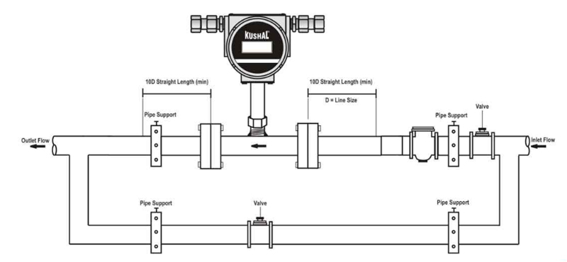
K-02 are 2 wire turbine flow transmitter specially used for various industrial application. The flowing media engages a vaned rotor causing it to rotate at an angular velocity proportional to flow rate. The Pick-up coil senses the spinning motion of the pipe & converts it into a pulsating electrical signal. Summation of the pulsating electrical signal is directly related to the total flow. The frequency is linearly proportional to flow rate which is converted to electrical signed 4-20 mA.
| Media | liquids (clear) |
| Viscosity | 100 cp max |
| Line Size | 40 NB to 150 NB |
| Display | 8x1 LCD - 4 digit for Flow Rate & 8 digit for totalised Flow (flow rate &totalised flow will be visible through toggle key) |
| Transmitter Electronic | 1) Integral 2) Remote |
| Remote Electronic Cable | 25 mtr max |
| Type of Output | 1) 4 to 20 mA DC 2) Pulse - 30mA Peak-Peak 3) Open Collector output |
| Calibration Range | As per requirement (Factory Calibrated) |
| Accuracy | +/- 1%F.S.(For 20 to 100% Flow) |
| Linerity | +/- 1% |
| Repeatability | +/- 1% |
| Process Temperature | 0 to 180°C max |
| Pressure Drop | Approx. 0.28 kg/cm2 at max. flow |
| Turn Down Ratio | 10:1 to 100:1 |
| Material of construction | Bearings - Tungsten Carbide Sleeve, V Jewel Rotor - SS 410 17.4 PH, Shaft - Tungsten Carbide, Body Support Flange SS |
| Power Supply | 1) 24 V DC, External |
| Power Consumption | < 1VA |
| Response Time | < 100mSec |
| Temperature Coefficients | +/- 0.1 % per OC |
| Transmitter Enclosure | Flame-proof, IP-65, IIA, IIB CMRI certified |
| Process Connections | ANSI 150 RF, flanged \, as per table B 16.5 BSP(M) Threaded(Upto 50 NB only) SS Tri-Clover (upto 50 NB only) |
| Mounting | In-Line (Horizontal OR Vertical) |
| Operating Conditions | Temperature 0 to 55°C , Humidity 5 to 95% on condensing |
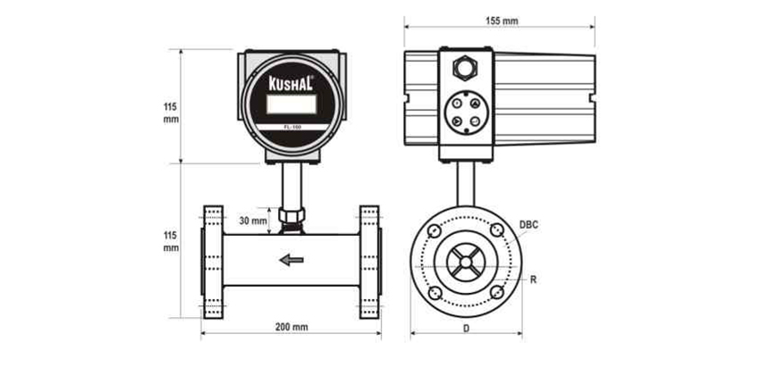
| Master Size | Flow Range | D |
C |
R |
DBC | d |
|
| m/hr | LPM | ||||||
| 15NB | 0.4 to 4.0 | 6.6 to 66.6 | 88.9 | 11.2 | 35.1 | 60.5 | 15.8 |
| 20NB | 0.8 to 8.0 | 13.3 to 133.3 | 98.6 | 12.7 | 42.9 | 69.9 | 15.8 |
| 25NB | 1.6 to 16.0 | 26.6 to 266.6 | 180.0 | 14.2 | 50.8 | 79.3 | 15.8 |
| 40NB | 3.4 to 34.0 | 56.6 to 566.6 | 127.0 | 17.5 | 73.2 | 98.6 | 15.8 |
| 50NB | 6.8 to 68.0 | 113.0 to 1133.0 | 152.4 | 19.1 | 90.2 | 120.7 | 15.8 |
| 80NB | 13.5 to 135.0 | 225.0 to 2250.0 | 190.5 | 23.9 | 127.0 | 152.4 | 19.1 |
| 100NB | 27.0 to 270.0 | 450.0 to 4500.0 | 228.6 | 23.9 | 157.2 | 190.5 | 19.1 |
| 150NB | 55.0 to 550.0 | 916.0 to 9166.00 | 279.4 | 25.4 | 215.9 | 241.3 | 22.4 |
D: OD of flange R: Dia of Raised Face
No. of Holes: 4 for 1/2" to 3" and 8 for 4" to 6"
C : Thickness of Flange DBC : Dia of Bolt Circle d : Size of Holes