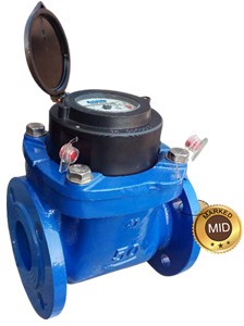
Belanto WP-SDC is TURBINE Woltman water meter with magnetic transmission, super dry type register for industrial and irrigation application has the sizes from Dn40 to Dn500 designed by Belanto and meets to the requirements of Directive 2004/22/EC on measuring instruments and of European Standard EN14154.
All the materials in contact with water, consciously selected by the known resistance to corrosion;
| SIZE | Dn40 to Dn125 | Dn150 to Dn200 | Dn250 to Dn500 |
| m3/pulse | 0.1 | 1 | 10 |
| 1 | 10 | 100 |
| Size | mm | 40 | 50 | 65 | 80 | 100 | 125 | 150 | 200 | 250 | 300 | 350 | 400 | 500 |
|---|---|---|---|---|---|---|---|---|---|---|---|---|---|---|
| R=Q3/Q1 | 50 | 80 | ||||||||||||
| Q4 | m3/h | 31,325 | 50 | 78,75 | 78,75 | 125 | 200 | 312,5 | 500 | 787,5 | 1250 | 1250 | 2000 | 3125 |
| Q3 | m3/h | 25 | 40 | 63 | 63 | 100 | 160 | 250 | 400 | 630 | 1000 | 1000 | 1600 | 2500 |
| Q2 | m3/h | 0,8 | 0,8 | 1,26 | 1,26 | 2 | 3,2 | 5 | 8 | 12.16 | 20 | 20 | 32 | 50 |
| Q1 | m3/h | 0,5 | 0,5 | 0, 7875 | 0,7875 | 1,25 | 2 | 3,125 | 5 | 7,875 | 12,5 | 12,5 | 20 | 312,5 |
| Max. Reading | m3 | 999999.999 | 9999999.99 | 99999999.9 | ||||||||||
| Min. Reading | m3 | 0,0005 | 0,005 | 0,05 | ||||||||||
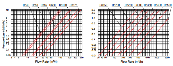
| Pressure Loss | P | 10 | 16 | 10 | 10 | 10 | 16 | 10 | 10 | 10 | 10 | 10 | 10 | 10 |
| Max. Pressure | MAP | MAP16 | ||||||||||||
| Max. Temperature | °C | T30 or T50 | ||||||||||||
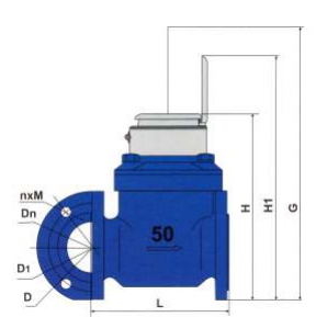
| DN | 40 | 50 | 65 | 80 | 100 | 125 | 150 | 200 | 250 | 300 | 350 | 400 | 500 |
|---|---|---|---|---|---|---|---|---|---|---|---|---|---|
| L | 260 | 200 | 200 | 225 | 250 | 250 | 300 | 350 | 450 | 500 | 500 | 600 | 800 |
| H | 225 | 252 | 262 | 272 | 282 | 297 | 341 | 371 | 480 | 516 | 560 | 647 | 785 |
| H1 | 303 | 339 | 349 | 359 | 369 | 384 | 428 | 458 | 576 | 603 | 603 | 723 | 838 |
| G | 360 | 400 | 400 | 400 | 400 | 400 | 500 | 500 | 710 | 730 | 730 | 830 | 930 |
| D | 150 | 165 | 185 | 200 | 220 | 250 | 285 | 340 | 405 | 460 | 520 | 580 | 715 |
| D1 | 110 | 150 | 145 | 160 | 180 | 210 | 240 | 295 | 355 | 410 | 470 | 525 | 650 |
| n x m | 4 x M16 | 4 x M16 | 4 x M16 | B x M16 | B x M16 | 8 x M16 | 12 x M20 | 12 x M20 | 12 x M24 | 12 x M24 | 12 x M24 | 16 x M27 | 20 x M30 |
| DN | 40 | 50 | 65 | 80 | 100 | 125 | 150 | 200 | 250 | 300 | 350 | 400 | 500 |
|---|---|---|---|---|---|---|---|---|---|---|---|---|---|
| L | x | 250 | 250 | 200 | 300 | x | x | 430 | x | x | x | 500 | 500 |
| L | x | 270 | 260 | 270 | 360 | x | x | x | x | x | x | x | x |
| L | x | 310 | x | 300 | 483 | x | x | x | x | x | x | x | x |
| L | x | x | x | 413 | x | x | x | x | x | x | x | x | x |
*Different Flange Standard for selecting such as: ISO 7005-2: 1998(E) PN10, ASME B16.1-Class125 working forB16.5-Class 150...
*Different Length of the Body as option